Joukovski
(Windows XP, Windows 7)
Generation
of Joukovski airfoils

|
Joukovski
(Windows XP, Windows 7)
Generation
of Joukovski airfoils
|
Introduction
Nikolai
Joukovski
(1847-1921) was a Russian scientist and a pionneer in the field of hyro and aero dynamics.
His early studies
were on the Magnus effect produced by a rotating cylinder in a wind
flow. In
1902 he built the first wind tunnel. He founded in 1904, near Moscow,
the first
aerodynamic research institute in Europe, became the famous TsAGI in
December
1918 by decree of the Soviet government.
Among
his many
works in physics and mathematics, he is known in particular for
determining the
geometry of airfoils using a mathematical tool based on the conformal
mapping
of a circle.
While
these airfoils
offers very interesting properties, while at least for a range of low
Reynolds
numbers corresponding to the models, they seem to have been forgotten
in favor
of wing sections developed for real aviation. Moreover, it appears that
the
performances of the wing sections are directly based on the value of
the
Reynolds number. And an airfoil which gives excellent results on a
plane or a
glider with a large Reynolds number can have a catastrophic behavior on
a model
where the value of the chord of the wing is small and / or the speed of
relative wind is low.
In
fact, we do
not find in the literature the coordinates of Joukovski wing sections
while
those of NACA, Wortmann, Eppler ... are widely available. Joukovski
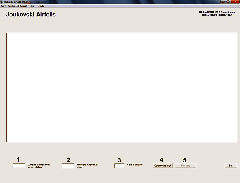
software
calculates the coordinates of these wing sections by simply introducing
the
value of the relative thickness and the value of the maximum curvature
of the
mean line of the wing sections.
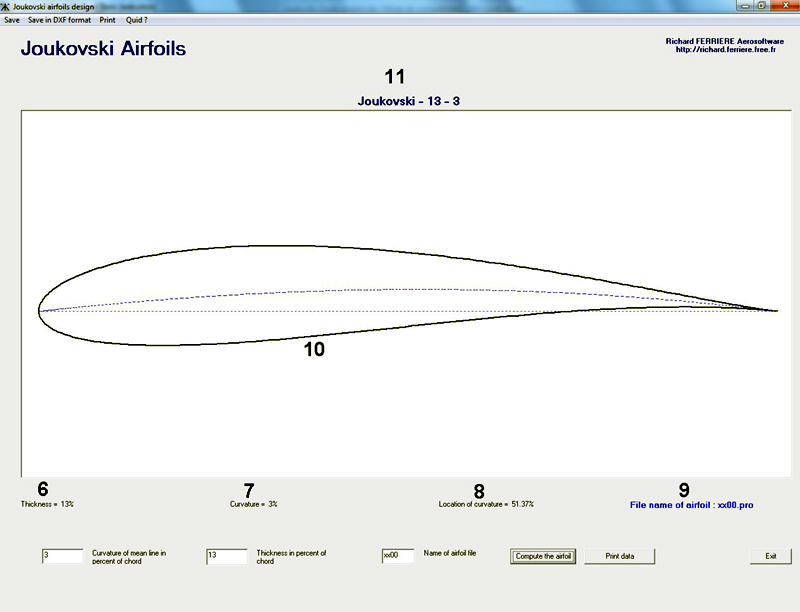
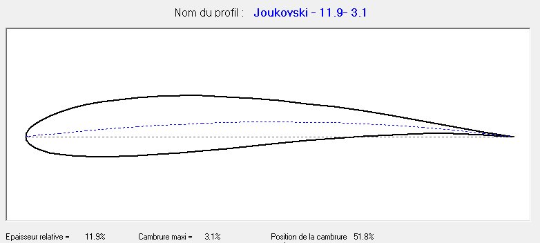
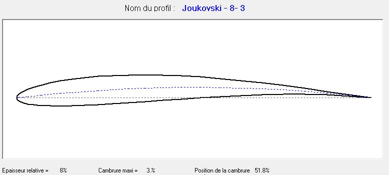
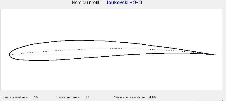
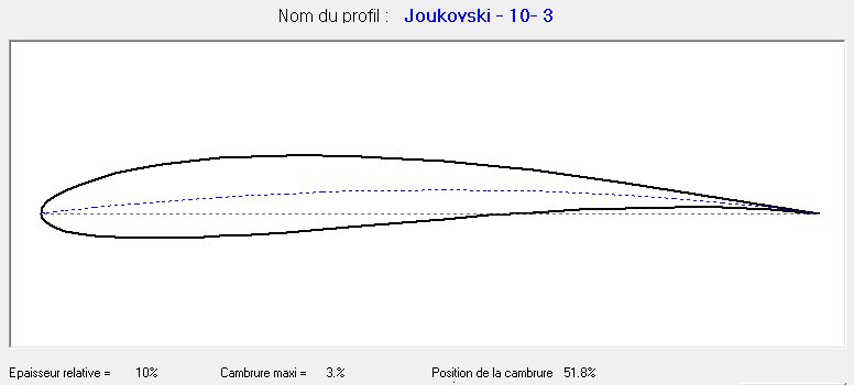
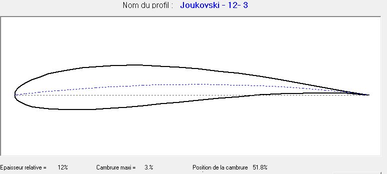
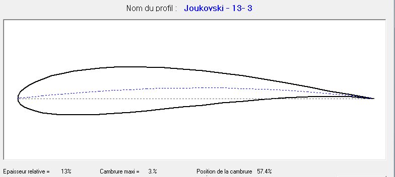
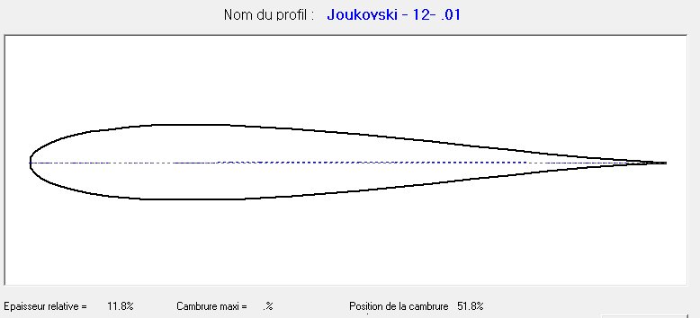
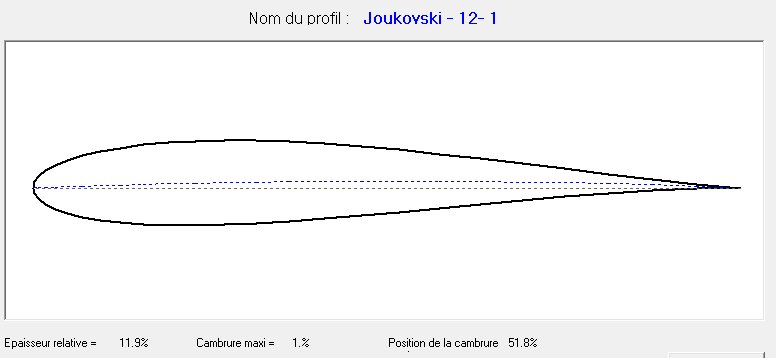
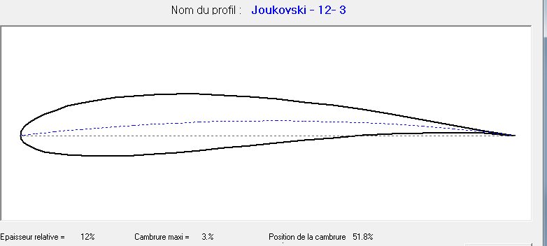
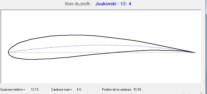
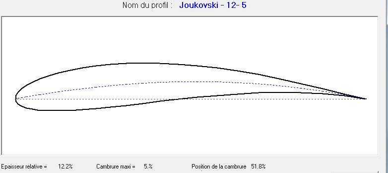
Clicking on command 4 runs the calculation of the file. The value of the relative thickness appears at 6, the curvature value at 7 and the position of the camber along the chord at 8. The name of the file containing coordinates of the wing section at 9, the pattern of the wing section 10. Finally in 11, the profile name is indicated : it is composed by the name Joukovski, the value of the relative thickness and the maximum camber (eg: Joukovski-13-3).
At the top of
the window, drop-down menus appear for
recording and
printing of the calculated wing
section
The Save
menu allows to record wing section coordinates in a ".pro" format
that can be read with a text editor like NotePad for example
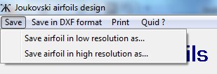
Two options are available:
- Save in "low resolution" in a ". pro" format ( directly usable
with Wings 2.12).
The wing section is described by 50 dots. The wing section file is
called
" jk00.pro" for example
- Save in "high resolution" in a ". pro" format. The wing section is
described by 360 dots.
The wing section file is called "zjk00.pro" for example, the letter z
added to the name is used to distinguish between high and low
resolution of
wing section.
Save in DXF format menu allows you to record the coordinates of the calculated wing section in a ".dxf" format recognized by most of CAD softwares like Autocad, Solidworks and software control of digital milling machines
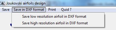
Again two options are available
to save the wing section in low and high resolution.
- One can specify the value of
the chord of the wing section. By default this value is proposed to
100, it can
be modified without limitation of dimensions.
- The other option is used to
assign a scale factor. Default factor is 1. This factor can be modified.
The
Print menu provides two options
too.
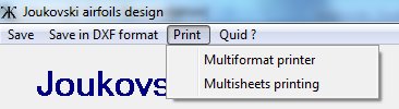
-
Multi-format printing option to
print
the drawing with high resolution by setting the value of the chord of
the
airfoil. Its possible to choose the
printer format from A4 to A0. Moreover, if the format
of the printer is
less than the size of a drawing a scale reduction is requested.
-
Printing
multisheets,
this option is for
those
who
have
only
A4
printer
but
want to
print
patterns
larger
than
the
printable
area
for
A4
"portrait".
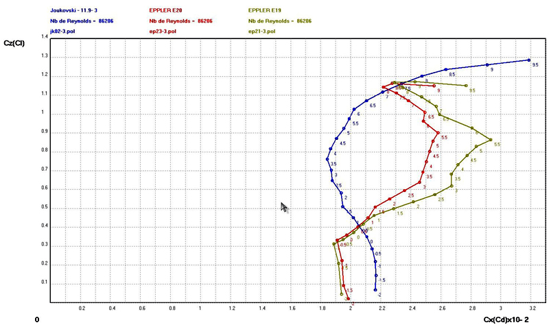
Comparative
evaluation of Joukovski
airfoils performances

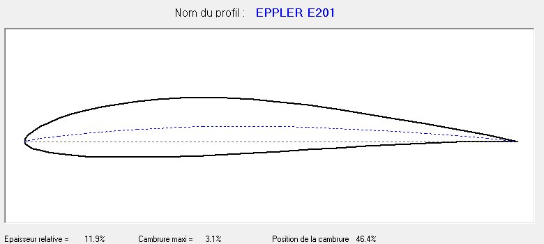
Eppler
195 and
201 airfoils are often considered as a reference by models designers
Re=80206 (chord=250mm,
v=5m/s)
Re=120689 (chord=250mm,
v=7m/s)

We
note that, for
very low speeds (5-7 m/s), Eppler 195 and 201 have an irregular polar
curve
with an sharp kink point at 7 ° incidence for a Cl max= 1.1.
While the
Joukovski polar is regular, without
inflection, and Cd min approximatively equal to 1.3. For common incidence angle, the difference of Cd values between Joukowski and Eppler airfoils is quite high.
Re=172413 (chord=250mm,
v=10m/s)
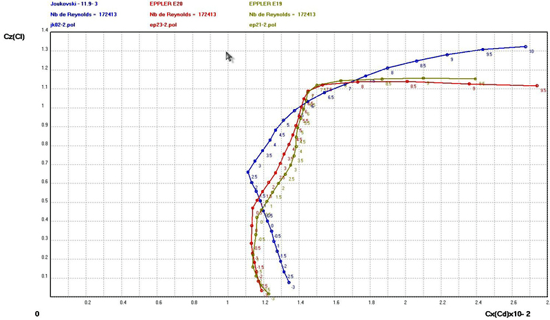
Re=258620
(chord=250mm, v=15m/s)
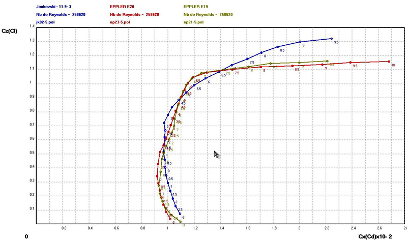
Between
10 m/s
and 15 m/s, Joukovski airfoil is
better than the Eppler airfoils especially for high incidence angle
Re=344827
(chord=250mm, v=20m/s)

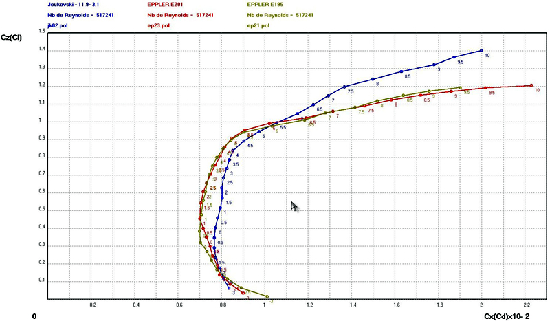
At
20
m/s
the
three
airfoils
exhibit
behaviour
nearly
equivalent
except
for
higher
incidences
where
Joukovski
appears
better
at
Cl level.
At
30
m/s,
the Eppler
airfoils (Cd
~
0.7)
are
more
efficient
than
the
Joukovski
(Cd
~
0.8),
which takes the
advantage
in
terms of
Cl for
incidence
angle
above
5.5°
Conclusions :
-
training aircraft,
-
gliders for slope soaring with
slow winds,
-
towing airplanes by providing a
wide speed range
-
for motorgliders, the high lift
coefficients associated with a moderate drag will offer a good rate of
climb.
- In terms of construction, rounded nose facilitates the achievement and the strength of the leading edge along the wing. They are also well suited for wings with high aspect ratio where extreme wing section works with low Reynolds number.
•
Variation of the polar curve of Joukovski airfoils versus thickness
for a
constant curvature value .(Re=172,413)
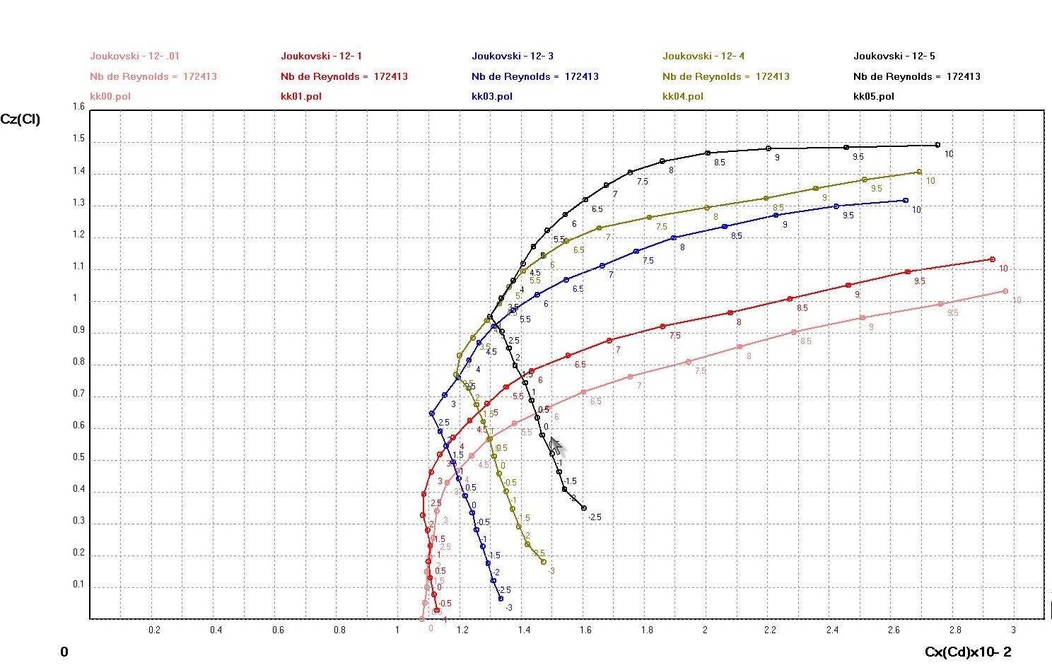
•
Variation of the polar curve of Joukovski airfoils versus curvature
value
for a constant thickness.(Re=172,413)